



首页 >>
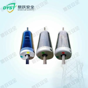
名称:Distributed Fault Location Monitoring Device
型号:
I. Requirements Analysis With the increasing number of high-voltage long-distance overhead transmission lines, these lines serve as the vital link for energy transmission and form the foundation for the safe and stable operation of the entire system. Should a fault occur on a transmission line, it is imperative to locate the fault point as quickly as possible, eliminate the fault, and restore power supply. However, high-voltage and ultra-high-voltage transmission lines are often exposed to diver
产品详情
I. Requirements Analysis
With the increasing number of high-voltage long-distance overhead transmission lines, these lines serve as the vital link for energy transmission and form the foundation for the safe and stable operation of the entire system. Should a fault occur on a transmission line, it is imperative to locate the fault point as quickly as possible, eliminate the fault, and restore power supply. However, high-voltage and ultra-high-voltage transmission lines are often exposed to diverse environments and span vast geographical areas, operating under harsh conditions. Consequently, they are also the most frequent sites of faults within the power system. Rapidly and accurately locating the fault point after a line failure is crucial not only for timely repairs and swift power restoration but also for the overall safety, stability, and economical operation of the entire power system.
II. Working Principle
The distributed fault location monitoring device for transmission lines employs distributed traveling wave measurement technology. Monitoring terminals are distributed along the transmission line conductors, capturing power frequency fault signals and traveling wave fault signals near the fault point at high potential. These signals are transmitted back to the backend data center via wireless methods such as 4G/5G. After comprehensive analysis by the data center, the fault location can be rapidly and accurately determined based on distinct fault characteristics. This enhances fault location accuracy, thereby improving patrol efficiency. Additionally, the system captures transient fault traveling waveforms to intelligently distinguish between lightning-induced and non-lightning-induced faults, as well as whether lightning strikes involve direct hits or counterstrikes. Diagnostic results are presented via web and SMS notifications to users, facilitating timely repairs and ensuring the secure, stable operation of the entire power grid.
III. Features and Functions
1. Basic Configuration for Fault Location Monitoring: Main Control Unit, Fault Location Monitoring Unit, Communication Unit, Inductive Power Harvesting Unit, Solar Power Supply Unit, Mounting Bracket, and Auxiliary Materials;
2. Detect and calculate fault distances: Accurately detect and record the distance of single-phase ground faults, phase-to-phase short circuits, open circuits, and instantaneous faults in real time.
3. High-Precision Fault Location: Accurately identifies the fault section on transmission lines with sectionalization reliability exceeding 99%.
4. Accuracy within 300 meters: Capable of precisely pinpointing transmission line fault locations with a positioning error of 300 meters.
5. Fault Cause Identification Function: Capable of distinguishing between lightning-induced faults and non-lightning-induced faults, with an accuracy rate exceeding 95% for such identification.
6. High identification accuracy: Capable of distinguishing between bypass faults and counterstrike faults, with lightning strike fault identification accuracy exceeding 90%.
7. Dual RAM Recording Technology: Utilizes dual RAM recording technology to eliminate transient signal "dead zones" and prevent missed fault data caused by lightning current interference.
8. Capable of online recording of lightning current on power lines, locating lightning strike points, and compiling statistics on the number of strikes;
9. Supports online detection of line load current, including scheduled transmission and on-demand retrieval of load current data;
10. The software features automatic fault detection, alarm output, and data file storage capabilities.
11. 4G/5G Wireless Transmission: Encrypted transmission and measurement over 4G/5G networks.
12. Supports remote upgrades: Enables remote parameter configuration and software upgrade functionality.
IV. Technical Specifications
| Serial Number | Category | Project | |
| 1 | Overall Performance | Complete System Configuration | Master Control Unit, Fault Location Monitoring Unit, Communication Unit, Inductive Power Harvesting Unit, Solar Power Supply Unit, Installation Accessories. |
| 2 | Overall quality | Less than 15 kg | |
| 3 | Material | Aluminum die-cast machine body | |
| 4 | Fault Location Monitoring Unit | Fault Location Sensor | Positioning reliability ≥99%; Positioning error ≤100 meters |
| 5 | Detect line length | 30 kilometers | |
| 6 | Broadband Traveling Wave Sensor | 1 kHz to 2 MHz | |
| 7 | Traveling wave sampling rate | ≥5MHz | |
| 8 | Single-wire fault current measurement range | 10A to 15,000A (RMS) | |
| 9 | Continuous recording duration of traveling wave current | ≥1000μs | |
| 10 | Communication Unit | Communication method | All-network compatible 4G/5G/WiFi wireless transmission |
| 11 | Data Security | Communication with the main server can utilize a dedicated VPN channel, with optional encrypted transmission. | |
| 12 | Access Protocol | Compatible with monitoring platforms of provincial power companies such as China Southern Power Grid and State Grid | |
| 13 | Power Supply Unit | Power Supply Method | Inductive power extraction and solar power extraction, system-coupled power extraction operates within a normal working current range of 30 to 1000 amperes. |
| 14 | Power supply duration | The power supply requirement ensures the device can operate normally for 30 days without illumination. | |
| 15 | Other parameters | Work Environment | Operating temperature: -40 to +70°C; Relative humidity: 5 to 99% RH |
| 16 | Overall service life | Over 8 years | |
| 17 | Protection Rating | IP66 |